A Flexible Unified Architecture for Point-to-Point Digital Microwave Radios
Release Date:2013-05-20
By Thanh Nguyen, Ying Shen and Andrey Kochetkov

Introduction
4G wireless networks are the next wave of mobile multimedia networks, and 4G LTE is fast becoming a reality. The backhaul point-to-point microwave radio is a key part of a 4G LTE network and is important to the overall success of the network.
Point-to-point microwave radios have gone from being all-indoor radios to being split-mount and outdoor radios. In the past, most microwave radios comprised rack-mounted indoor radio units. Bulky elliptical waveguides had to be used to connect these units to antennas on a tower or rooftop. Industry later devised a split-mount radio system comprising an indoor unit (IDU) and outdoor unit (ODU), both of which are mounted onto the back of the antenna or connected to the antenna using a short waveguide. Today, industry is gravitating towards an all outdoor radio unit (AOU) mounted on the back of the antenna. These AOUs contain the RF components as well as the circuitry for tributary interfaces, modem, and network management.
In a 4G network rollout, operators want their microwave equipment to be scalable and interchangeable and to share common elements for all capacities and frequency bands. From the vendor’s perspective, an architecture that supports various platforms with as many common denominators as possible is also highly preferable. This has become a key design requirement for point-to-point microwave radio. Here we give an overview of design commonalities in transceiver architecture, mechanical concept, antenna interface and duplexer, and software and production test flow.
Common Transceiver
Fig. 1 shows a traditional split radio with an IDU, ODU, and antenna. An IDU typically comprises a modem, mux circuits, a controller, and a power module. The ODU up-converts the IF signal received from the IDU into an RF signal. The ODU then amplifies the RF signal before sending it to the antenna. The RF signal received from the antenna is down-converted to an IF signal and passed through a multistage gain control circuit before being sent back to the IDU.

An AOU integrates modem and network functionalities with IF and RF functionalities. IF and RF signal processing is similar to that in an ODU; therefore, a transceiver that is common to both platforms is a logical design requirement. Such a transceiver has the following characteristics:
● It supports both I/Q interface for the AOU and TX IF interface for the ODU.
● It has two detectors in the transmitter chain. The first detector is placed in the ODU to compensate cable loss, and it is bypassed in the AOU application. The second detector is used to detect the level of the power amplifier (PA) and also for alarm purposes in both applications.
● It supports wide filter bandwidths for digital predistortion (DPD). Open loop DPD parameters are characterized through calibration and then applied to the modem look-up table (LUT) to correct the non-linearity of the PA.
● It has a PA bias control to reduce the bias when the power level is low.
● It supports RF loopback for self-diagnosis.
● It supports on-board local frequency reference. Alternatively, it supports a reference from the digital board in the AOU or IDU for future hitless and coherent applications.
Common Mechanical Concept
Fig. 2 shows the ODU and AOU. The transceiver is mounted to a casting for heat sinking. The interface card is mounted to the same casting as the transceiver. The transceiver and interface card are connected through a pair of mating connectors. One connector is installed on the top of the interface card, and the other is installed on the bottom of the transceiver.
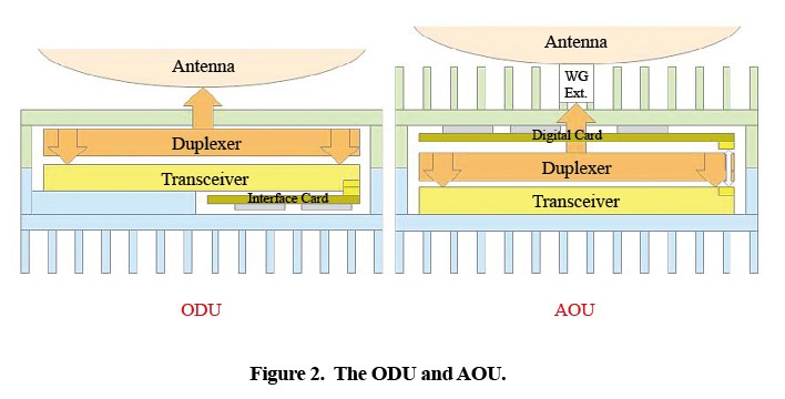
The AOU physical cross-section has the same concept. The transceiver is mounted to a casting for heat sinking (as in the ODU). In the AOU, the digital card is mounted to its own casting. The transceiver has a dual footprint for the connector: A footprint on the bottom is used in the ODU, and another on the top is used in the AOU. A flexible circuit is used in the AOU to bridge the gap between the connectors of the digital card and the transceiver. By simply relocating the connector, the ODU and AOU have the same transceiver.
Common Duplexer for the ODU and AOU
The transmit and receive ports of a duplexer connect to the transmit and receive ports of a transceiver. Because the transceiver and duplexer are common to the ODU and AOU, the connection between the two is also common. In the ODU, the common duplexer common port extends from a hole in the ODU enclosure and connects to the antenna. For an AOU, a waveguide extension is added to bridge the distance between the duplexer and the antenna.
Common Antenna Interface and Common Mounting Mechanics
The common port of a duplexer connects to the antenna. It pass transmit and receive signals between the antenna and the ODU and AOU. This connection is a waveguide connection. For an ODU, the antenna feed mates with the duplexer through an opening in the casting of the common duplexer port. For an AOU, the antenna feed mates to the waveguide extension which mates to the duplexer. Both the ODU and AOU castings have four mounting posts of identical dimensions so that the same antenna can be used on both radio units.
Common Software
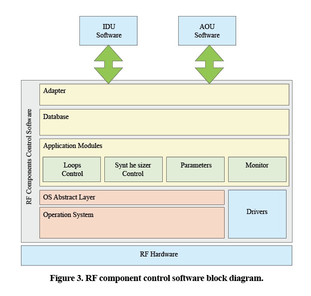
Common software is used to control RF hardware and provide a generic interface for system configuration. The software design has the following common features for both ODU and AOU:
● application modules are isolated from the operation system by using an OS abstraction layer. Software for controlling RF components can be based on different operation systems.
● a generic interface is used to communicate with an IDU via a telemetry channel (in the case of an ODU) or is used to communicate with other modules that are not controlled by RF components control software via an inter-task communication mechanism (in the case of an AOU).
● bandwidth and modulation-dependent data is stored separately from the RF component control software. This data is stored in the form of bandwidth/modulation profiles that can be updated separately using software.Each frequency band has its own set of bandwidth/modulation profiles, and the RF component control software does not need to be changed when hardware with a new frequency band is introduced.
Common Test Flow
A common test flow is used for both ODU and AOU. The ODU has a duplexer, transceiver (TRX), interface (INFC) module, and ODU mechanics. The duplexer, TRX and INFC first go through their own module pass/fail test stations. Then, the TRX, INFC and ODU mechanics are integrated into a radio frequency unit (RFU). This unit undergoes RF and DPD calibration and is then integrated with a duplexer so that it is now dependent on a frequency band. It then goes through a final ODU test flow. The AOU shares the same TRX and duplexer with the ODU and has a similar test flow.
Summary
ODU and AOU radio platforms can have a flexible, unified architecture by exploiting common design elements in radio hardware, software, and test flow. This design conserves valuable area on the transceiver and allows the transceiver size to be minimized. Cost is also saved by reducing the size of mechanical components. The use of a common transceiver, duplexer, and antenna greatly reduces the number of unique components that must be designed, tested, and stocked. This significantly improves time to market and minimizes the need for design resources. Greater volumes have been passing through common manufacturing assemblies, and greater attention has been paid to the economics of scale.
relative articles